

[cl-popup show_on=”image” image=”53″ align=”right” ]
 [/cl-popup]
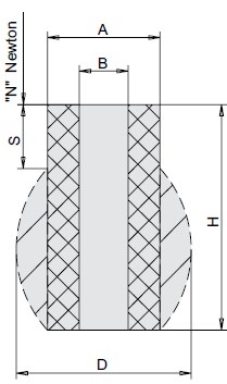
TECHNICAL DRAWING

[cl-popup show_on=”image” image=”53″ align=”right” ][/cl-popup]
TECHNICAL DRAWING
Calculation example
Elastic stroke = material thickness (s) + setback (k) +
punch penetration depth into the die (t) +
voltage (min. 10% Lo)
Example: s = 3, k = 1, t = 1.5, 10%, Lo = 2.5
Elastic stroke s=3+1+1.5+2.5 = 8mm
Notes please keep the maximum load in mind.
admissible on the spring.
Length of the pin for the spring
The length of the pin for the spring (L1) is a function of:
a – of the punch length (L)
b – of the thickness of the guide plate (L2)
c – of the punch retraction (k) relative to the guide plate
Pin length for spring L1 = Punch length + setback – thickness
Guide plates L1 = L + K – L2
This elastic element is superior to usual spring systems in:
– safety
– precision
- overall dimensions
– speed of replacement
and offers the advantage of a wide and gradual adjustability of the preload without requiring the disassembly of the mold. For elastic columns larger than 1.5 x d1, the insertion of a centering pin with a smooth surface, for example a straight pin, is recommended.
N. B. The tables of mechanical and chemical resistance characteristics have been removed from the original DU PONT documentation.
N forces add up when springs are mounted in parallel. Heights add up when springs are mounted stacked; on the other hand, the N force remains unchanged.
In this case, it is advisable to place a steel washer between one spring and the other.
Like traditional springs, polyurethane springs also experience a length settlement that occurs during the first few hours of operation and, under the worst conditions, can reach 6% – 8% of the spring’s free height.
If installation, load calculations, and compression stroke are done to perfection, polyurethane springs easily exceed one million cycles.
N.B.: the height of the die springs must never be greater than twice the diameter A